- 您现在的位置:买卖IC网 > Sheet目录2002 > LICAL-TRC-MT (Linx Technologies Inc)IC TRANSCODER MT BI-DIR 20-SSOP
–
24
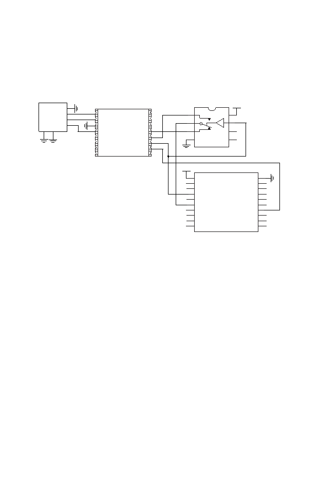
Serial Interface Connections
The serial interface on the MT Series can be connected to any device
capable of serial communication, including microcontrollers, RS-232 drivers
and computers. The figure below gives an example of connecting the MT
to the Linx QS Series USB module for connection to a computer.
The USB module follows the RS-232 convention of using separate lines
for data input and data output while the transcoder has a single line for all
data. This requires a switch to alternatively connect the transcoder’s SER_
IO line to the data lines on the module.
The RTS line is used to throw the switch as well as to activate the CRT/
LRN line placing the transcoder into Serial Mode. This gives the PC the
ability to control when communication is initiated.
The MODE_IND line will go high when the transcoder is prepared to send
data, so the CTS line on the USB module is used to monitor the MODE_
IND line. This allows the computer to know when to throw the switch and
look for data from the transcoder.
One point of note is that voltage translation may be necessary if the 5V
USB module is used to communicate with a transcoder operating at 3V.
There are many components and methods for implementing level shifting,
so it is up to the designer to determine the best solution for the product.
USBDP
USBDM
GND
DSR
DATA_IN
DATA_OUT
RTS
CTS
DTR
TX_IND
VCC
SUSP_IND
RX_IND
485_TX
RI
DCD
1
2
3
4
5
6
7
89
10
11
12
13
14
15
16
VCC
D6
D7
CRT/LRN
ENC_SEL
SER_IO
CONFIRM
TR_PDN
TR_SEL
TR_DATA
GND
D5
D4
D3
LATCH
SEL_BAUD
MODE_IND
D2
D1
D0
1
2
3
4
5
6
7
8
9
10
11
12
13
14
15
16
17
18
19
20
LICAL-TRC-MT
SDM-USB-QS
8
7
6
5
1
2
3
4
V+
NC
GND
MAX4544
USB Type B
Connector
GND
5V
DAT -
DAT+
GND
GSHD
1
2
3
4
5
6
VCC
Figure 19: MT Series Transcoder Serial Interface to a PC
Figure 20: MT Series Transcoder Serial Interface Engine Command Set
发布紧急采购,3分钟左右您将得到回复。
相关PDF资料
LT1331CNW#PBF
IC TXRX 5V/3V RS232 28-DIP
LT1341CG#TRPBF
IC TXRX 5V RS232 SHUTDOWN 28SSOP
LT1342CG
IC TXRX 5V RS232 W/3VLOGC 28SSOP
LT1794CSW#PBF
IC OPAMP 200MHZ DUAL 20-SOIC
LT6301IFE
IC XDSL LINE DRIVER DUAL 28TSSOP
LT8500IUHH#TRPBF
IC PWM GENERATOR 56-QFN
LTC1096IN8#PBF
IC A/D CONV 8BIT SRL IN/OUT 8DIP
LTC1099ACN#PBF
IC A/D CONV 8BIT HI-SPEED 20-DIP
相关代理商/技术参数
LI-CAM-AR0331
功能描述:视频模块 Aptina AR0331 HD WDR CAMERA BOARD
RoHS:否 制造商:Leopard Imaging 产品:Camera Modules 支持的视频格式:H.264, MPEG4, MJPEG 每秒帧数:30 显示分辨率—像素:1920 x 1080 接口类型:RS-485, USB 工作电源电压:12 V 最大工作温度:+ 45 C 尺寸:113.3 mm x 57.6 mm x 32.2 mm
LI-CAM-AR0331-324-1.8
功能描述:视频模块 Aptina AR0331 IP CAMERA BOARD
RoHS:否 制造商:Leopard Imaging 产品:Camera Modules 支持的视频格式:H.264, MPEG4, MJPEG 每秒帧数:30 显示分辨率—像素:1920 x 1080 接口类型:RS-485, USB 工作电源电压:12 V 最大工作温度:+ 45 C 尺寸:113.3 mm x 57.6 mm x 32.2 mm
LI-CAMFLEX
功能描述:程序设计器配件 2" CAMERA EXTENSION CABLE RoHS:否 制造商:Lattice 产品:ispDOWNLOAD Cables 用于:In-system Programming
LI-CAM-IMX036
功能描述:视频模块 Sony iMX036 HD IP CAMERA BOARD
RoHS:否 制造商:Leopard Imaging 产品:Camera Modules 支持的视频格式:H.264, MPEG4, MJPEG 每秒帧数:30 显示分辨率—像素:1920 x 1080 接口类型:RS-485, USB 工作电源电压:12 V 最大工作温度:+ 45 C 尺寸:113.3 mm x 57.6 mm x 32.2 mm
LI-CAM-IMX036-1.8
功能描述:视频模块 Sony IMX036 IP CAMERA BOARD
RoHS:否 制造商:Leopard Imaging 产品:Camera Modules 支持的视频格式:H.264, MPEG4, MJPEG 每秒帧数:30 显示分辨率—像素:1920 x 1080 接口类型:RS-485, USB 工作电源电压:12 V 最大工作温度:+ 45 C 尺寸:113.3 mm x 57.6 mm x 32.2 mm
LI-CAM-IMX104-1.8
功能描述:视频模块 Sony IMX104 IP CAMERA BOARD
RoHS:否 制造商:Leopard Imaging 产品:Camera Modules 支持的视频格式:H.264, MPEG4, MJPEG 每秒帧数:30 显示分辨率—像素:1920 x 1080 接口类型:RS-485, USB 工作电源电压:12 V 最大工作温度:+ 45 C 尺寸:113.3 mm x 57.6 mm x 32.2 mm
LI-CAM-IMX104-P33
功能描述:视频模块 Sony IMX104 IP CAMERA BOARD
RoHS:否 制造商:Leopard Imaging 产品:Camera Modules 支持的视频格式:H.264, MPEG4, MJPEG 每秒帧数:30 显示分辨率—像素:1920 x 1080 接口类型:RS-485, USB 工作电源电压:12 V 最大工作温度:+ 45 C 尺寸:113.3 mm x 57.6 mm x 32.2 mm
LI-CAM-IMX122-P33
功能描述:视频模块 Sony IMX122 IP CAMERA BOARD
RoHS:否 制造商:Leopard Imaging 产品:Camera Modules 支持的视频格式:H.264, MPEG4, MJPEG 每秒帧数:30 显示分辨率—像素:1920 x 1080 接口类型:RS-485, USB 工作电源电压:12 V 最大工作温度:+ 45 C 尺寸:113.3 mm x 57.6 mm x 32.2 mm